Entity Relationship Models and ER Diagrams
Entity Relationship Models and ER Diagrams
Entity Relationship Models
What are ER Models? - The Entity-Relationship (ER) model is a conceptual tool for representing data relationships in a relational database. It provides a high-level view of how entities (objects) relate to each other in the database.
Entities - An entity represents a real-world object or concept within the domain of the database system. It's something that can be distinctly identified. - Example: In a university database, entities could include Students, Professors, and Courses.
Attributes - Attributes are the properties or characteristics of an entity that hold values. Each attribute describes a particular aspect of the entity. - Example: For the Student entity, attributes could include StudentID, Name, Age, and Major.
Relationships - Relationships represent how entities are associated with one another. They illustrate the business rules or interactions between entities. - Example: A 'Enrolls' relationship might exist between the Student and Course entities, indicating that students enroll in courses.
ER Diagrams in Detail
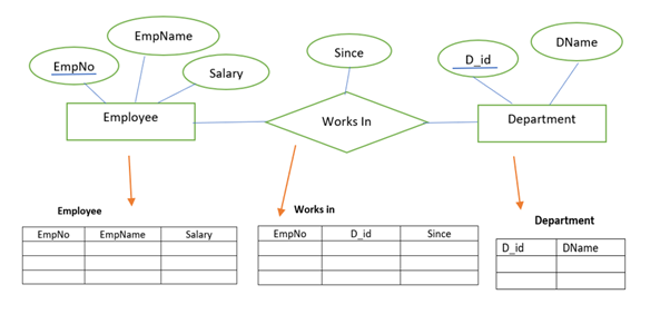
Components of an ER Diagram - Entity Sets: Represented by rectangles and labeled with the entity names.
-
Attributes: Circles or ovals connected to their respective entities, labeled with attribute names.
-
Relationships: Diamonds that connect entities, labeled with the relationship name.
Cardinality and Participation Cardinality: Indicates the number of entities that can be associated with another entity in a relationship. Common cardinalities include one-to-one, one-to-many, and many-to-many.
Participation: Specifies whether all entities are involved in the relationship (total participation) or some (partial participation).
Visual Representation of an ER Diagram
- Drawing Entities and Attributes
-
Start by identifying the entities in the system and list their attributes. Draw rectangles for entities and connect circles for attributes.
-
Identifying Relationships
-
Determine how entities are related and draw diamonds to represent these relationships. Connect the entities with lines to the relationship diamonds.
-
Defining Cardinality and Participation
- Use symbols or labels near the connections to indicate cardinality (e.g., 1:1, 1:N, N:M) and lines or arrows to show participation (e.g., a double line for total participation).
Connecting Entity and Relationship
-
Every relationship should connect two or more entities, indicating how instances of one entity are related to instances of another.
-
Example: In an Organization database, an 'Employee' relationship might connect the Department entity. This indicates that an employee works in a certain organization. The cardinality might be one-to-many (1:1), meaning an employee can work single department.
